

 English
 русский
 Español
 عربى
No. 8, Calle Duxiu San, Pueblo de Ganlin, Ciudad de Shengzhou, Ciudad de Shaoxing, Provincia de Zhejiang, China

Categoría de noticias
Categoría de producto
How to Design a BLDC Motor: A Complete Step-by-Step Engineering Guide for 2026
Contenido
- 1 Understand the BLDC Motor Before You Design One
- 2 Define the Design Requirements and Specification
- 3 Choose the Motor Topology
- 4 Design the Magnetic Circuit
- 5 Design the Stator and Winding
- 6 Design the Rotor and Mechanical Package
- 7 Design the Commutation and Drive Electronics
- 8 Design for Thermal Management
- 9 Prototype, Test, and Validate
- 10 Consider Manufacturing and Cost Early
- 11 Work with an Experienced BLDC Motor Manufacturer
Designing a brushless DC (BLDC) motor is a systematic engineering process that begins with a load specification, not with a magnet grade or a winding count. Get the specification right, and every following step becomes a structured trade-off; get it wrong, and no amount of magnetic or electronic refinement will recover the lost development time. In the experience of Shengzhou Jiangxin Motor Technology, a professional motor manufacturer with production in Shengzhou, Zhejiang, most unsuccessful BLDC projects trace back to an incomplete specification, an unstated environmental constraint, or an efficiency target that cannot be achieved inside the chosen envelope. This article lays out the complete design procedure for a three-phase BLDC motor: defining requirements, selecting the topology, designing the magnetic circuit, calculating windings, specifying commutation electronics, managing heat, validating prototypes, and preparing for manufacturing. The goal is to give design engineers and technical procurement teams a practical framework they can apply before the first magnet is ordered.
Understand the BLDC Motor Before You Design One
A BLDC motor is a permanent-magnet synchronous machine driven by an electronic inverter. The rotor carries permanent magnets, the stator carries the three-phase winding, and the controller continuously creates a stator field ahead of the rotor so that torque is produced without any mechanical contact. Because the commutator and brushes of a brushed DC motor are replaced by electronic switching, there are no brush losses, no carbon dust, and no sparking. For the designer, this changes the entire optimization space: efficiency improves by 10 to 20 percentage points at comparable power, service life is governed by bearings and insulation instead of brush wear, and motor behavior can be tuned by changing the control algorithm as well as the geometry.
Two commutation families dominate design practice. Six-step trapezoidal commutation energizes two motor phases at a time and electronically switches the energized set every 60 electrical degrees. It is simple, low-cost, and perfectly adequate for fixed-speed or lightly regulated fans, compressors, and pumps. Sinusoidal commutation, usually implemented as field-oriented control, applies time-varying currents with a sine profile to all three phases. It produces smoother torque, less acoustic noise, and better partial-load efficiency, which is why virtually all EC fan motors and modern air-cooler motors use sinusoidal control. The phrase "EC motor" simply means a brushless DC motor with the electronics integrated into the motor housing; you will hear the terms "BLDC" and "EC" used interchangeably, with the difference being emphasis rather than hardware.
| Motor technology | Commutation | Relative efficiency | Maintenance | Control complexity | Typical application |
|---|---|---|---|---|---|
| Brushed DC | Mechanical brushes | Medium | Brush replacement | Very simple | Power tools, starter motors |
| AC induction | Mains frequency slip | Medium-low at partial load | Low | Simple for fixed speed | Pumps, fans, compressors |
| BLDC / EC | Electronic inverter | High across load range | Very low | Requires controller | Fan motors, air coolers, EV auxiliaries, precision drives |
This comparison matters because the control electronics used for a BLDC motor are not an accessory bolted on afterward. They define the voltage stress on the winding insulation, the current waveform that heats the copper, the torque ripple that reaches the load, and the failure modes that the motor must survive. Consequently, the motor design and the drive design have to be developed together. A motor optimized for six-step operation will have a trapezoidal back-EMF shape; a motor intended for field-oriented control should have a sinusoidal back-EMF shape, which is established by magnet arc width and magnetization pattern. Trying to force one winding design to serve both strategies ends in noise, vibration, or unnecessary power loss.
Define the Design Requirements and Specification
The first design deliverable is not a three-dimensional model; it is a written specification. A complete specification fixes the operating window tightly enough that a motor manufacturer can quote a feasibility study, propose a slot and pole combination, and estimate cost without asking the customer nine clarifying questions. In the engineering reviews carried out at Jiangxin Motor, the projects that move fastest are the ones that arrive with a short but complete specification sheet: rated voltage, speed range, torque, duty cycle, envelope, ambient temperature, noise target, and target efficiency.
- Rated voltage and tolerance: a battery system has a wide range (for example 10.5 V to 13.8 V for a nominal 12 V) while a rectified mains supply has a narrower band; the winding and the controller must both survive the upper limit.
- Rated output power or continuous torque and speed: state which one is fixed at the design point, because a fan rated by power behaves completely differently from a conveyor rated by torque.
- Speed range: a fan may need 30% to 100% speed control, which changes the minimum back-EMF that a sensorless controller can measure.
- Duty cycle: continuous duty (S1) is the default for fans; an actuator or a coffee-grinder may be intermittent (S2 or S3) and can tolerate much higher current density.
- Mechanical envelope and shaft interface: maximum diameter, stack length, shaft extension, press-fit or keyway, and mounting bore pattern.
- Ambient environment: temperature, humidity, dust, and corrosive gas; a cattle-house fan motor faces ammonia and frequent washdowns, while an evaporative air cooler faces high humidity and condensing water.
- Acoustic noise limit in dB(A) at one meter, measured in the actual duct or housing.
- Efficiency target at the rated point and, for variable-speed products, at representative partial-load points.
- Expected lifetime and reliability, usually expressed in operating hours (10,000 h, 20,000 h) or number of starts.
- Applicable standards: product safety, EMC, insulation class, and the customer's internal approval criteria.
| Parameter | Target value | Design note |
|---|---|---|
| Rated voltage | 220 V AC rectified, about 310 V DC | Bus voltage drives the turn count |
| Rated output power | 150 W | At the aerodynamically rated speed |
| Rated speed | 1,350 r/min | Adjustable from 400 to 1,400 r/min |
| Continuous torque | 1.0 N·m | Corresponds to 150 W at 1,350 r/min |
| Peak torque | 1.5 N·m for 10 s | For grid dip and stall recovery |
| Efficiency | 82% minimum at rated point | Measured motor plus controller |
| Insulation class | Class B, 130 °C | Ambient 40 °C, 90 K rise |
| Noise | Maximum 55 dB(A) at 1 m | In a free-air duct |
| Protection class | IP44 | Dripping water and particles |
The load type mainly determines the torque envelope. A centrifugal fan follows affinity laws: flow is proportional to speed, pressure to speed squared, and shaft power to speed cubed. The motor torque demand therefore rises with the square of speed. At half speed, a fan requires only about one quarter of its rated torque; at high speed, the load torque is at its maximum. A positive-displacement pump or a conveyor, by contrast, demands constant torque across the speed range, so the motor must be designed for high current at low speed. This single distinction changes the thermal design, the magnet volume, and the control strategy.
Write the specification before the first CAD file, and lock it with a signature. In the Jiangxin Motor product development flow, every BLDC sample order is checked against a specification form before the winding schedule is released. If a parameter such as ambient temperature is missing, the sample is built under arbitrary assumptions and the qualification test fails later.
Choose the Motor Topology
The first architectural decision is between an inner-rotor and an external-rotor arrangement. The conclusion from decades of appliance motor development is clear: for direct-driven fans, air coolers, and blowers, an external-rotor BLDC motor is almost always the better choice. For shaft-coupled loads that run at high speed or require low rotor inertia, an inner-rotor motor remains the right choice.
An external-rotor motor has the stator in the center and the permanent magnets bonded or mounted on the inside of a cup-shaped rotor that spins around the stator. The cup can be extended axially to carry the fan blade directly, eliminating belts, pulleys, and gearboxes. The larger rotor diameter increases the lever arm on which the electromagnetic shear stress acts, so a given torque is achieved with less magnet volume and lower magnetic loading. Since the rotating mass is on the outside, the motor naturally behaves like a flywheel, which smooths the torque pulsations of a fan load rather than amplifying them.
- External-rotor advantage: direct-drive fan hub integration, high torque density at low speed, short axial length, and natural air-moving action of the rotor surface.
- External-rotor limitation: higher moment of inertia, less convenient cooling of the stator through the shaft, and a more involved balancing procedure for large diameters.
- Inner-rotor advantage: small rotor inertia, easy coupling to a spindle or belt, and simpler sealing around a small shaft.
- Inner-rotor limitation: needs a gearbox or belt for low-speed fan loads, and a longer axial package for the same torque.
Once the topology is fixed, the slot and pole combination is the second-most fundamental choice. For small external-rotor BLDC motors, three-phase stators with concentrated windings dominate: each stator tooth carries one coil, there are no winding overhangs between poles, and the coils can be wound on bobbins by automatic machines. The two most widely used combinations are 12 slots with 10 rotor poles (12S10P) and 12 slots with 14 rotor poles (12S14P). Both produce a harmonic-rich waveform well suited to six-step or field-oriented control, and both give a high least common multiple between slots and poles, which breaks the cogging torque into many small events rather than one large one. A 9-slot, 6-pole combination is occasionally used for very small motors because it needs less copper, but it has a higher unbalanced magnetic pull and is less forgiving of manufacturing asymmetry.
For fans, choose a pole count that keeps the electrical frequency in a comfortable range. At 1,400 r/min, a 10-pole motor has an electrical frequency of about 117 Hz; a 14-pole motor about 163 Hz. Higher electrical frequency means more core loss in the stator lamination and more switching events per revolution in the controller, so very high pole counts should be avoided for high-speed designs. Conversely, too few poles forces a thicker back iron to carry the rotor flux.
An example of the external-rotor approach at production scale is the Jiangxin external-rotor BLDC air cooler motor line. The 149 mm frame size is built as a 12-slot stator with a cup-shaped rotor designed to match the impeller of an evaporative cooler, and it is available in power steps from 600 W to 850 W at 220 V.
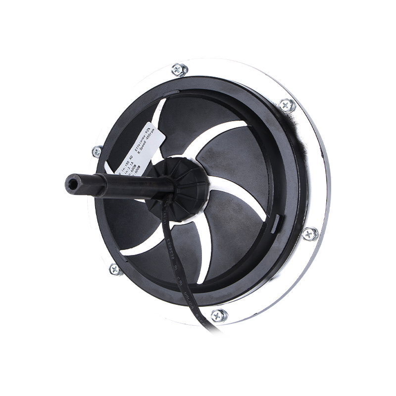 Jiangxin DC149 220V 850W External-Rotor BLDC Air Cooler MotorThis production-scale external-rotor motor drives evaporative cooler impellers directly, offering up to 850 W at 220 V with high efficiency and long life, matching the preceding discussion on magnetic circuit performance in large air-moving applications.View Product →
Design the Magnetic Circuit
With the topology fixed, the magnetic circuit defines the torque and efficiency potential. The dominant choices are magnet grade, magnet pole arc and thickness, air-gap length, stator lamination grade, and the geometry of the flux path.
Select the Magnet Grade
Sintered neodymium-iron-boron (NdFeB) is the standard for most utility BLDC motors because its maximum energy product, from roughly 35 MGOe (N35) to over 50 MGOe (N52), can produce a 0.8 to 1.1 T air-gap flux density in a compact stator. The magnet temperature rating has to match the worst-case winding temperature: standard N grades tolerate about 80 °C, while H, SH, and UH grades extend the operating range to 120 °C, 150 °C, and 180 °C respectively. Ferrite magnets are much cheaper but have an energy product an order of magnitude lower; they are used only when cost pressure is extreme, the ambient temperature is high, or the motor diameter is not restricted.
Set the Air Gap and Pole Arc
The air-gap flux density is selected mainly by cost and efficiency. In a small fan BLDC, a reasonable target is 0.6 to 0.85 T in the air gap. The air gap itself ranges from 0.3 mm for a 60 mm motor to 0.8 mm for a 200 mm motor; a larger air gap reduces the risk of rotor-stator contact in production and lowers cogging torque, but it forces more magnet material to establish the same flux density. The magnet arc width controls the shape of the back-EMF wave. A pole arc of about 120 electrical degrees yields a trapezoidal back-EMF suitable for six-step commutation; pole arcs of 150 to 170 degrees with graded magnetization yield a nearly sinusoidal back-EMF suitable for field-oriented control.
Minimize Cogging Torque
Cogging torque is the most visible nuisance in low-speed fan operation. It is the preference of the magnets to align with the stator teeth, and it creates vibration, acoustic noise, and speed pulsations at low RPM. Three countermeasures are practical in mass production. First, choose a slot and pole combination with a high least common multiple such as 12S10P or 12S14P. Second, magnetize the magnets with a skew or use skewed stator laminations. Third, design the pole arc slightly larger or smaller than an integer number of slot pitches. Each countermeasure adds a small manufacturing cost, so the best design uses the slot and pole combination to solve most of the problem and adds skew only when the noise target is severe.
At this stage, finite-element analysis is standard. A two-dimensional magnetostatic simulation of the cross-section gives the flux density map, the back-EMF waveform, and the cogging torque value. The designer should also calculate the theoretical maximum torque from the rotor volume: for a small air-cooled BLDC, the electromagnetic shear stress, which represents the torque per unit rotor surface area, falls in the range of 10 to 30 kN/m². If the target torque requires a shear stress beyond that range, the motor needs more magnet material, better cooling, or a larger frame.
Design the Stator and Winding
The winding is where the electrical specification becomes copper and insulation. The stator core is built from non-oriented electrical steel laminations in thicknesses of 0.35 to 0.5 mm. Grades such as 50JN470 or 50JN600 are typical for appliance motors; thinner 0.35 mm steel reduces iron loss at high electrical frequency but costs more in stamping and stacking. Lamination coatings must resist the curing temperature of the winding resin; the standard C5 insulating coating is adequate to 200 °C for short intervals.
The turn count is the single most important winding parameter. It sets the voltage constant, that is, how much back-EMF the motor generates at a given speed. A high number of turns yields a high voltage constant, which is good for torque at low speed but limits the maximum speed because the back-EMF approaches the bus voltage. A low number of turns yields a low voltage constant, which allows high speed but forces high current for a given torque and produces high loss.
For a first-order estimate, set the line-to-line back-EMF peak at the continuous operating point to about 80% to 90% of the DC bus voltage when using six-step commutation, leaving the remaining voltage for the winding resistance drop and the inverter drop. For sinusoidal field-oriented control, the relationship depends on the modulation depth, but the same principle applies: the total back-EMF plus resistive drop at maximum speed must stay below the inverter's linear output range. In practice, BLDC designers calculate the back-EMF constant from the finite-element model, build a prototype, spin it at a known speed, and measure the voltage; the turn count is then scaled inversely with the square of the diameter ratio if the frame must be changed.
Wire gauge selection follows from current density. For a naturally cooled fan motor with continuous duty, keep the RMS current density in the range of 4 to 6 A/mm². If the motor is integrated into a duct where airflow passes over the housing, such as an evaporative air cooler or an EC fan, 6 to 8 A/mm² is practical; intermittent duty allows as much as 10 A/mm² for short periods. As an example, a 150 W motor with a 310 V bus drawing an RMS phase current of about 0.7 A would need roughly 0.17 mm² of copper per turn for a 4.5 A/mm² current density, which is around AWG 25. Stranded or parallel wires are used when a single strand becomes too stiff or too thick to wind on a small tooth.
Star and delta connections behave differently. Star (wye) connection is standard for three-phase BLDC windings: the phase voltage is lower, the insulation stress is smaller, and the third-harmonic currents that circulate in a delta winding are eliminated. Delta windings are rare in BLDC fan motors precisely because they generate circulating harmonic currents that add loss and heat without contributing torque. Unless there is a specific reason, the winding should be a star-connected three-phase design.
Copper fill factor, the ratio of the copper cross-section to the total slot area, has a strong effect on efficiency. Random-wound concentrated coils reach 0.4 to 0.5; bobbin-wound coils with pre-formed wire can reach 0.5 to 0.6. A higher fill factor lowers the winding resistance and therefore the copper loss, but it requires harder wire and more expensive winding equipment. The designer should check whether the cost of premium fill is justified by the efficiency target; if the target is modest, a simpler needle-wound bobbin at 0.45 fill may be sufficient.
Design the Rotor and Mechanical Package
The rotor carries the magnets and delivers the torque to the shaft or hub. In an external-rotor motor, the rotor is a drawn or machined steel cup performing three functions: it forms the magnetic return path, it retains the magnets, and it carries the fan blade or coupling interface. The steel thickness in the magnetic path, the back iron, must be sufficient to conduct the magnet flux without saturation. For a 10-pole rotor of about 130 mm diameter with N35 magnets, a back iron of 4 to 6 mm keeps the flux density at approximately 1.5 T, close to the saturation limit of electrical steel. Thicker back iron adds weight, inertia, and material cost.
Surface-mounted magnets are held onto the inner bore of the rotor cup by structural adhesive. For fan applications with moderate tip speeds, adhesive retention is normally sufficient. For higher speeds, a stainless steel retaining sleeve or a carbon-fiber band resists the centrifugal expansion of the magnets. Post-assembly magnetization in a dedicated fixture is the preferred mass-production method because it avoids handling magnetized components and guarantees magnetic synchrony.
The bearing arrangement determines lifetime, noise, and price. Ball bearings are used when the axial load or the expected life exceeds what sleeve bearings can provide; they also survive higher ambient temperatures because they release heat better through the outer race. Sleeve bearings are attractive in low-cost fan motors where the shaft is vertical or the axial load is negligible, but their life declines sharply with temperature and contamination. For a motor intended to run 20,000 hours in an air cooler in a dusty environment, specify sealed ball bearings with lifetime grease.
Mechanical balance is especially critical in large-diameter external rotors. An unbalanced rotor produces vibration at the rotational frequency, which is transmitted to the fan blade and becomes audible noise. For small fan motors, ISO 1940 balance grade G6.3 is commonly accepted; for quiet residential products, grade G2.5 is specified. Dynamic balancing in two planes is a standard production operation for rotors whose width is greater than 20% of their diameter.
Finally, the shaft and mounting interface must respect the actual assembly process. Straight-through shafts with a D-cut are easily pressed into the fan hub; shafts with a keyway concentrate stress and require a tight key fit for fan couplings. Mounting flanges should be designed around the housing bore pattern of the final appliance, because any adapter adds axial length and cost. The designer must specify concentricity and perpendicularity tolerances between the shaft, the rotor cup, and the stator bore; a typical dimensional budget for a small fan motor is 0.02 mm radial runout between shaft and stator bore, and 0.05 mm axial face runout.
Design the Commutation and Drive Electronics
No BLDC motor is complete without its drive electronics. The controller performs the commutation, governs the speed, and protects the motor. The motor and controller must be designed as a single system because the controller sets the voltage stress, the current waveform, and the safety limits.
Choose the Commutation Scheme
The most economical commutation method remains six-step block commutation with Hall sensors. Three Hall-effect switch devices are placed on the stator at exactly 120 electrical degrees of spacing; they detect the rotor magnetic poles and trigger the six inverter switching events per electrical period. Hall sensors simplify startup and work reliably at standstill, which matters for applications that must start under load. The cost penalty is three sensors plus a small magnet ring, which is negligible in the total bill of materials but adds assembly steps.
Sensorless six-step commutation removes the Hall sensors and estimates the rotor position from the zero-crossings of the back-EMF. The motor then needs only three wires and a controller, a very clean product architecture for sealed or potted motors. The drawback is that back-EMF does not exist at standstill; the controller uses an alignment pulse to bring the rotor to a known position and then runs an open-loop acceleration ramp until the back-EMF is measurable. Sensorless control is the standard choice for fan motors that always start unloaded.
For applications demanding very low noise and zero speed ripple, field-oriented control is the best solution. Field-oriented control regulates the orthogonal components of the stator current to keep the phase currents sinusoidal with respect to the rotor angle. It eliminates the six-step torque pulsations, reduces acoustic noise, and improves partial-load efficiency. The implementation cost is a faster microcontroller and high-resolution current sensing on the phase lines.
Build the Inverter and Protection
The inverter stage is a three-phase full bridge. For motors up to about 1 kW at mains voltage, MOSFETs are the dominant switching device; above that, IGBTs become attractive. The switching frequency should be set to at least 16 to 20 kHz, above the audible range, to avoid the metallic whine caused by the PWM carrier. A ceramic or film capacitor across the DC bus absorbs the switching ripple; an electrolytic capacitor provides bus holdup time. The controller should monitor the DC bus voltage, phase currents, and winding temperature, and implement undervoltage lockout, overcurrent trip, and overtemperature cutoff. For fans with a locked rotor, the controller should detect the condition and retry after a short delay rather than burning the winding.
All these functions live on a control board that eventually becomes part of the motor housing, which means the thermal design of the controller belongs to the same budget as the motor losses. The MOSFET junction-to-case and case-to-ambient thermal resistances, the PCB copper area, and the air movement over the control board all have to be verified by test. A common mistake is to design an extremely efficient motor and a controller that dissipates 15 W of its own in a small sealed enclosure; the combined system then fails temperature qualification.
If you are not familiar with the details of commutation sequencing and PWM strategy, a short primer on how a BLDC motor controller works is useful before committing to an electronics architecture; the control method directly affects the motor specification.
The Jiangxin EC fan motor range is a production example of this integrated design: the electronic control board, the three-phase stator, and the rotor are packaged inside one housing, so the customer wires only the supply and receives a variable-speed motor ready for a control input.
 Jiangxin ECF-155-10 380V 2200W EC Fan MotorA high-power integrated EC fan motor with built-in protections and wide voltage tolerance, suited for HVAC and industrial ventilation. Its packaged design underscores the importance of thermal management and reliability in variable-speed fan systems.View Product →
Design for Thermal Management
Thermal management, not electrical performance, is the reason most BLDC prototypes need a second iteration. The winding temperature limit is the hard constraint: the insulation class sets the maximum allowable total temperature, which for Class B is 130 °C, Class F 155 °C, and Class H 180 °C. With a 40 °C ambient, a Class B motor may rise 90 K at the winding hot spot. If the predicted temperature rise approaches that limit, the motor must be redesigned with lower loss density rather than merely given a bigger exterior fan.
The losses available for conversion into heat are the copper loss from the winding resistance, the iron loss in the stator laminations, the friction and windage loss of the bearings and rotor, and the switching and conduction loss of the controller. At low speed and high torque, copper loss dominates; at high speed with light load, the iron loss and switching loss dominate. The efficiency map over the operating range should be calculated and measured at the design points, because the rated point alone does not reveal a thermal bottleneck at partial speed.
Heat leaves a BLDC motor by conduction through the stator core into the housing and by convection from the outer surfaces. In an external-rotor fan motor, the rotor cup is moving air, so the natural convection coefficient at the rotor surface is significantly higher than for a static enclosure. This creates a favorable design loop: the higher the speed, the stronger the cooling, which partially compensates for the higher iron and switching losses at high speed. Nevertheless, the stator coils are buried inside a layer of steel and winding resin, so the bottleneck is the temperature drop from the copper to the housing. Good thermal contact between the stator stack and the housing is more valuable than a thick aluminum heat sink on the bracket; use a high-thermal-conductivity resin or a shrink-fit housing when the budget permits.
Quantify the thermal path rather than guessing. Measure the winding temperature with thermocouples embedded in the coil end turns, or with a resistance-based method, mapping the temperature rise at the rated point, the overload point, and the minimum-speed point where self-cooling is weakest. Infrared cameras are useful for identifying local hot spots in the inverter and the laminations, but they cannot see the winding hot spot inside the stator; a thermocouple is the reference method.
For outdoor equipment such as evaporative air coolers and poultry-house fans, the summer ambient temperature can approach 45 °C to 55 °C depending on the region, and the motor may be mounted directly in the airflow. Specify the ambient temperature in the procurement contract; the difference between a 40 °C and a 50 °C ambient specification changes the magnet grade and the copper fill factor required, and therefore changes the price.
Prototype, Test, and Validate
A BLDC motor that exists only in simulation has no value. A physical prototype must be built early, instrumented, and measured. The development plan should reserve two to four iteration rounds, because the first prototype almost never meets the full specification at the same time.
- Winding resistance and phase inductance: measure with an LCR meter at 1 kHz; the values should match the calculation within 10%, otherwise the fill factor or turn count is off.
- Back-EMF waveform: spin the rotor with a drive motor at a fixed speed and record the line-to-line voltage; check the peak amplitude and the wave shape, trapezoidal for six-step and sinusoidal for field-oriented control.
- No-load test: run the motor with its controller and measure the no-load current and speed; the difference between no-load speed and rated speed indicates the magnetic performance.
- Load performance: couple the motor to a dynamometer and record torque, speed, input power, output power, and efficiency across the load range.
- Efficiency map: a map over speed and torque, used to validate the controller settings such as advance angle and current loops, and to confirm the partial-load target.
- Temperature rise: apply the rated load in the intended ambient chamber; log the winding temperature until steady state, with a pass criterion of at least 15 K below the insulation limit for continuous duty.
- Noise and vibration: measure acoustic noise in the actual duct at one meter, and run a fast Fourier transform to separate the electromagnetic noise (electrical frequency harmonics and slot-passing frequency) from the mechanical noise (bearing and imbalance).
- Insulation test: apply a high-potential test of approximately two times the rated voltage plus 1,000 V AC for one minute; check the insulation resistance with a megohmmeter.
- Reliability: a continuous run of 1,000 to 2,000 hours at rated load, with periodic measurement of input power, verifies that magnets, adhesives, and bearings are stable.
The test data must be compared against the specification in a written design review gate. Launching a production batch on the basis of a single motor's performance is unacceptable because winding tolerance, magnet variance, and bearing preload differences will spread the performance. In the Jiangxin Motor sample approval process, at least two or three samples are measured end-of-line, and the median value plus the spread must remain inside the specification window.
Qualification tests for fan motors should also include stall recovery, locked-rotor current measurement, input voltage dips and surges, and temperature cycling, since a stalled fan can overheat in seconds. If the target product is sold in multiple countries, the insulation and EMC tests must be repeated for the respective standards and the motor data sheets updated accordingly.
Consider Manufacturing and Cost Early
A motor design that cannot be manufactured cost-effectively will never leave the laboratory. Cost drivers in a small BLDC motor are not distributed equally, and the design decisions made in the early stages have outsized influence.
| Cost item | Typical share of motor cost | Design or procurement lever |
|---|---|---|
| Magnet (NdFeB) | 20% to 35% | Choose N35 or N38 instead of N42+ if the flux density budget allows; small gains in magnet grade are disproportionately expensive |
| Lamination steel and stamping | 15% to 25% | Choose a standard lamination shape shared across several frame sizes; avoid laser-cut prototypes in mass production |
| Copper winding | 10% to 15% | A higher fill factor needs automated winding; a moderate fill with standard wire lowers equipment cost |
| Bearings | 8% to 15% | Ball bearings are a price driver; use sleeve bearings only if the life target permits |
| Controller electronics | 10% to 20% | Sensorless six-step is the cheapest control; field-oriented control adds a microcontroller and current sensors |
| Assembly and testing | 10% to 15% | Design magnet insertion to be press-fixture friendly; use automatic balancing stations in line |
Magnet cost is the easiest place to destroy a budget. NdFeB prices fluctuate with the supply of rare-earth elements, and a motor that uses 20% more magnet volume than necessary absorbs a permanent cost penalty. Larger pole arcs improve the back-EMF shape but consume expensive magnetic material; the torque gain is linear in magnet thickness but it saturates quickly in arc width. Simulate the magnet thickness sensitivity at the beginning of the project; the difference between 3 mm and 4 mm magnets can be visually concerning but electrically negligible, and it may decide whether the product reaches its price target.
Winding automation is the second key decision. Concentrated windings on toothed stators can be wound by needle winding machines at high repeatability. A design with a high number of turns and fine wire is slow to wind; reducing the turns by selecting a higher magnet grade is often cheaper than paying for an extra winding minute per stator. Conversely, a design with thick wire that cannot be wound without parallel strands may degrade the fill factor; specify parallel fine strands instead of one thick wire when the coil former cannot accept it.
Manufacturing tolerances in the rotor also create yield losses. Magnet adhesive squeeze-out, uneven magnet seating, and out-of-round rotor cups cause imbalance and noise. The design should include locating features such as shoulder faces and pilot bores in the rotor cup, keeping the dimensional tolerance consistent between the stator bore and the rotor bore. Finally, every complete motor is tested end-of-line; the test plan should be part of the production line, not an afterthought in a separate lab. Automated test stations measure winding resistance, insulation, no-load current, and rated-load response, and they sort out the units that fall outside the specification window before they reach the customer.
Work with an Experienced BLDC Motor Manufacturer
Not every project justifies building an in-house motor development laboratory. The economic crossover is driven by volume, lead time, and internal competence. A company producing 10,000 fans per year will rarely recover the cost of a finite-element license, a dynamometer, a magnetizing fixture, and the engineering time needed to bring a motor from concept to production. An experienced motor manufacturer can take a specification directly to prototype, and that is exactly how most small and medium equipment makers bring BLDC products to market.
Jiangxin Motor Technology, operating from its plant in Shengzhou, Zhejiang, is one such manufacturing partner. The company develops and builds AC and DC motors and micro motors, has passed ISO 9001 quality management system certification, and exports its products to more than 60 countries. Its product portfolio includes external-rotor BLDC air cooler motors, EC fan motors, cattle-house fan motors, glass-reinforced plastic fan motors, and concrete-mixer motors, which means the engineering team has already optimized slot and pole combinations and control parameters for applications very close to a typical fan or air-moving product. The Jiangxin 198 mm frame external-rotor BLDC air cooler motor, for example, delivers 1,500 W at 220 V and is used in large evaporative coolers, showing how an established design platform can be scaled upward rather than reinvented.
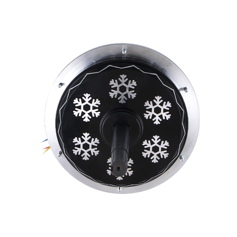 Jiangxin DC198 220V 1500W External-Rotor BLDC Air Cooler MotorA heavy-duty external-rotor BLDC motor rated at 1500 W for large evaporative coolers and ventilation systems, with F-class insulation and IP54 protection. It exemplifies a scalable design platform when briefing manufacturers for BLDC projects.View Product →
When you brief a manufacturer for a BLDC design project, provide the following material in the initial inquiry:
- The load profile: torque versus speed, duty cycle, and any overload events.
- The electrical input: DC bus voltage or mains voltage and frequency.
- The mechanical envelope: maximum diameter, stack length, shaft dimensions, mounting pattern, and the fan hub or impeller interface.
- The environment: ambient temperature range, humidity, dust, chemical exposure, and whether the motor is sealed or ventilated.
- The targets that matter most: efficiency, noise, life, or first cost. Rank them, because a motor cannot maximize all four at once.
- The standards the final product must meet, including safety and EMC directives.
The manufacturer's response to this brief should include a feasibility statement, a proposed slot and pole combination, predicted performance values at the rated point, estimated dimensions, a cooling concept, and a development schedule. In the Jiangxin process, the next step is a design review between the customer's engineering team and the motor factory's development staff, where the magnet grade, the winding turns, the controller strategy, and the reliability samples are agreed in writing. Only after that review does the factory release the winding schedule and start tooling. This collaborative gate prevents the most expensive form of ambiguity, the difference between what the customer's marketing department believes and what the motor can physically deliver.
If you have a preliminary specification on hand, the fastest way to move forward is to discuss the load profile and envelope with the factory's engineering department through the contact channel; even a rough sketch of the fan curve helps the designers identify the right first iteration.
The successful BLDC motor design is not the product of a single insight; it is the accumulated result of disciplined decisions at every stage of the loop: specification, topology, magnetic circuit, winding, commutation, thermal management, validation, and manufacturing. The specification caps the achievable performance. The topology sets the physical architecture. The magnetic circuit and winding define efficiency and torque. The controller decides noise, startup behavior, and protection, and the production process determines the repeatability and the cost. Each discipline can be reduced to a manageable set of choices, and each choice can be checked against the written specification. A motor manufacturer with experience in serial production can compress the two-year development cycle into a few months, because the failure modes, the test limits, and the manufacturing tolerances are already known. Use the specification sheet, use the test gates, and use a production partner early enough to make the design manufacturable from the first prototype.
Relacionado Productos
-
 Motor de refrigeración por aire BLDC externo DC149 de 220 V/700 W
-
 Motor enfriador de aire BLDC externo DC149 de 220 V y 850 W
-
 Motor enfriador de aire BLDC externo DC149 de 220 V y 600 W
-
 Motor enfriador de aire evaporativo trifásico YS90L-4 de 380 V y 1500 W
-
 Motor enfriador de aire evaporativo trifásico YS100L-4 de 380 V y 2200 W
-
 Motor enfriador de aire evaporativo trifásico YS90L-4 de 380 V y 1500 W
-
 Motor mezclador de hormigón portátil YY71-2 de 230 V y 650 W
-
 Motor mezclador de hormigón portátil YY71-2 de 110 V y 800 W
 ¿Listo para Personalizar
Sus Productos de Motores?

Somos fabricantes de motores profesionales que entregamos energía potente, estable y eficiente núcleos para todas las industrias a través de la artesanía de precisión y la innovación.
Contáctenos
-
 Móvil:+86 13575536911
-
 Teléfono:+86 18357538240
-
 Whatsapp:+8618357538240
-
 Correo electrónico:betty@dbjxmotor.com
-
 Dirección de la empresa
Derechos de autor © por Shengzhou Jiangxin Motor Technology Co., Ltd. Todos los derechos reservados.
